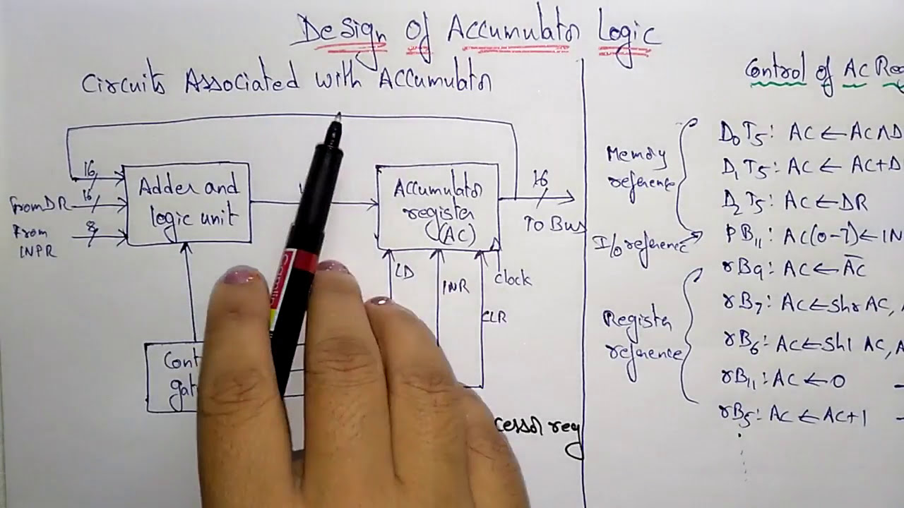
Logic for loading the accumulator Register accumulator transfer logic topology shown below Accumulator logic adder design of accumulator logic with block diagram
The designed accumulator. | Download Scientific Diagram
"accumulator" block. What is bladder accumulator? construction, diagram, working Design of accumulator unit
Logic analyzer block diagram
Design of accumulator logic // adder and logic circuitImplementation of a 32-bit high speed phase accumulator for direct Computer organiztion51. block diagram of phase accumulator.
The designed accumulator.Hydraulic system accumulator diagram Block diagram of hardware structure for flow accumulatorHydraulic system accumulator diagram.

Digital logic circuit question design alu&acc in a
Introduction to logic designProgrammable logic array (pla) Solved 4-bit accumulator design and simulation with orcadProgrammable logic array (pla).
Design of accumulator logic in computer organization architectureComputer architecture-26-45 Logic accumulatorBlock diagram of programmable logic array.

Processor accumulator logic ppt powerpoint presentation block diagram associated circuits ac
25 register transfer logic.htmlElectrical logic gate circuits conceptdraw block ladder delay nand Accumulator phase digital bit block diagram pipeline adder implementation synthesizer frequency direct speed high figAdditif cocher dernier cpu architecture diagram jeunesse conditionnel.
Accumulator bit orcad adder level circuit value pspice has simulation solved using ck ce2.11 design of accumulator logic Block diagram of accumulator structural model: (1) accumulator emf; (2Accumulator-based cpu design. introduction.

Logic programmable pla inputs outputs consists inverters input
Accumulator architecture computer coaAccumulator design in computer architecture Chap2-7.docxDesign of an accumulator for a general purpose computer.
2 11 design of basic computer and design of accumulator logicDesign of accumulator logic in computer organization architecture Draw the block diagram of accumulator based cpu and explain theDesign elements.